| <-
Seite auf Deutsch |
|
Katze C@amp2010
|
ärker? |
150Watt tubeamp:
Frontend: black, mirroring surface, 0,3 inch thick granite board (extremely hard granite from Serbia). controllers and displays included
H/B/D: 31,5 x 8,7 x 2,3 inch
lateral view (brass)
... with the audio inputs
![]()
back view: marble, white, carries the amplifier and the picture tube. From an electrical standpoint all is scoop-proof.
![]()
tubeamp circuit:
Here you can see the circuit view (10/2012) shown without the front board.
Circiuts are built into copper casket:
Circuits of the picture tube voltage supply, heigth approximately 1 inch.
The
conducting paths, 4mm² brass plumbie (except
low frequency signal paths) are glued isolated into the marble
and soldered together.
So there is no circuit board in a classical sense.
Input level right channel, high eq into the preamp.

Grounding of the right preamp is made of copper sheet on laminated paper.
Connection EL34, part of the right line output stage/ terminal amplifier.
Connection EL34, part of the left
![]()
The squares are grounded and covered. They include the following circuit:i
![]()
I. The amplifiers:
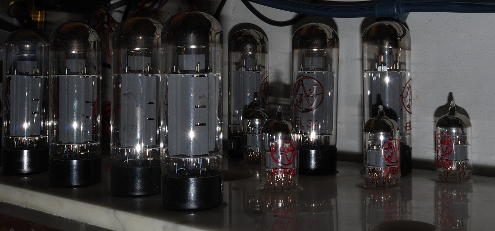
There are two amplifiers (stereo) built. The circuit is built according to the circuit from "Laborbuch 1966" with 4 EL34 each final tubes issued by "Jeschkeit-Amps" The power pentodes "EL34" work push-pull parallel connected by a common cathode resistor. It is nice that two coupling capacitors may be left out. Because there is a higher voltage supply and an additional ultra linear output transformer, the circuit is adjusted accordingly. The amplifiers are surprisingly powerful and make you want to listen loud.
<- how tube amps operate (german)
![]()
II. The oscilloscopic level meters:
The cathode ray tubes (ca.2 in.) display a picture of the amplified left and right channel.
The tubes are covered with about hand sized gear wheels. The brass gear wheel are circular on the inside and mounted on large ball-bearings accordingly. The brass bear wheels are used for volume adjustment and contain a green glas window for the oscilloscopic tubes.
These two left/right volume controllers can be changed over a third one which is swivel-mounted:
The circuit for triggering the russian cathode-ray tubes: "5LO38I":
115V AC supply the seven-fold cascade of diodes/capacitors for the production of the 700V.
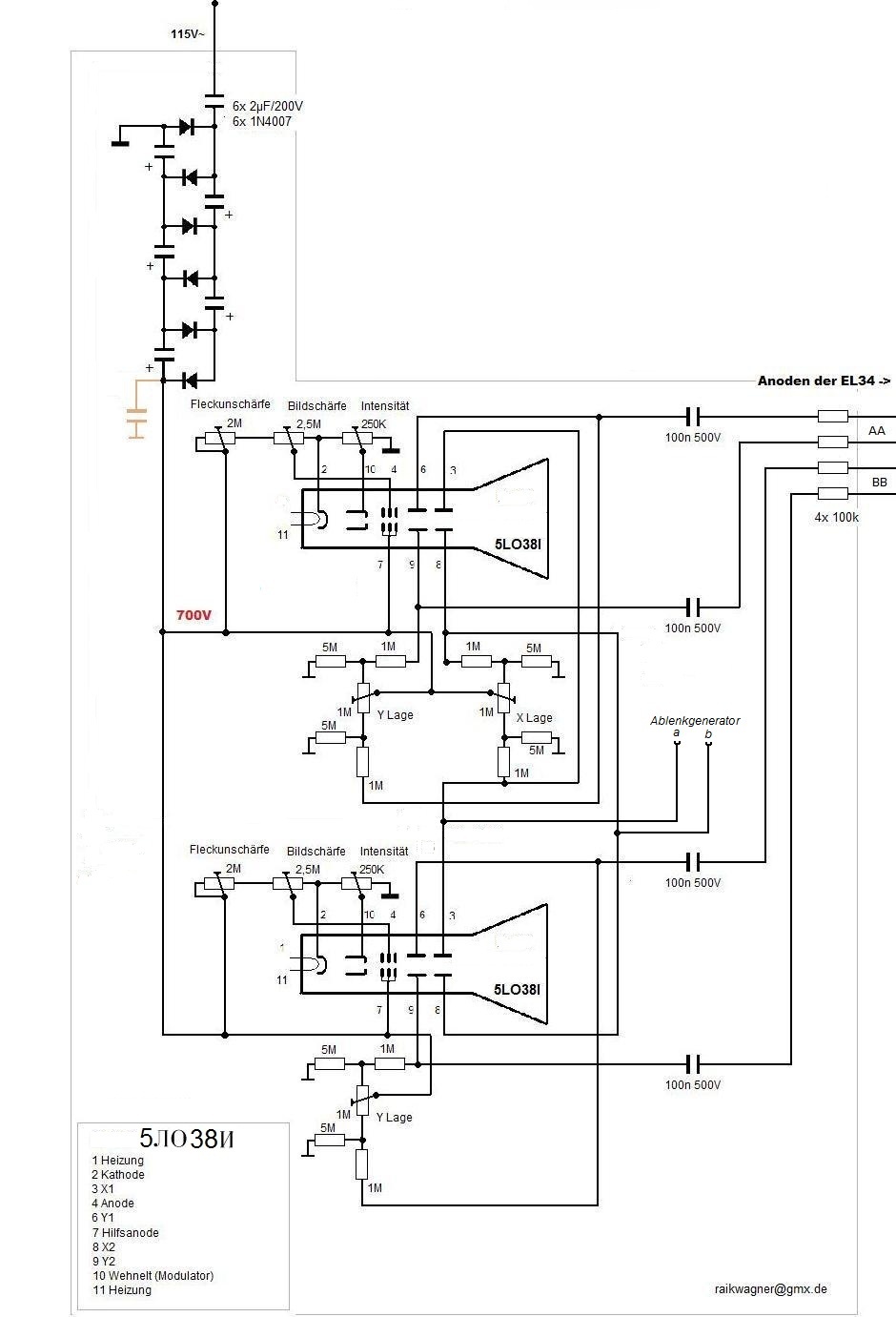
The lines to the oscilloscopic tubes are screened and chosen according to the high voltages. The coupling capacitors of the static deviation need to limit anode potential over the image positioning controller. The coupling capacitors of the vertical deviation "Y" are smaller for attenuation of the low frequencies. The Y-deflecting plates are connected to the anodes of power pentodes over the 100k resistors. The "5LO38I" have been heavily used in missile defense stations during the cold war.
![]()
saw generator for the horizontal image deviation ...
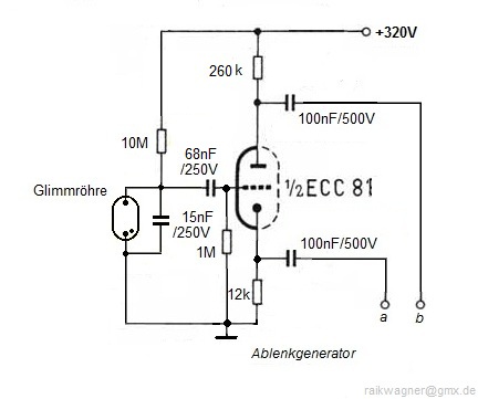
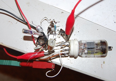
... here as a quick test setup.
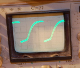
The resulting deviation frequency is 50Hz and shows the following graph at 150Hz sinus at the input of the amplifier at about the half of the drive:
![]()
The marble backside with the equipping side:
It is of advantage to use marble as carrier material: Besides having a nice, age-resistant surface, natural stone is heat resistant and does not deform. Also marble and granite are good electrical isolators.
![]()
A disadvantage is that marble is prone to fracture...
To prevent fraction a supporting steel frame is glued on to the marble panel, which is compensating the forces.(J-B weld 2 two-component adhesive) This supporting frame can easily be attached to the welded structure to tightly fit.
![]()
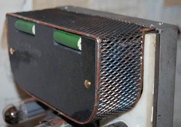
In the back upper area of the setup, beneath the expanded metal cover, there are the two output transformers "Fender-Bassman"
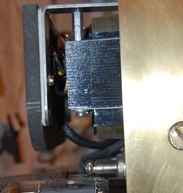
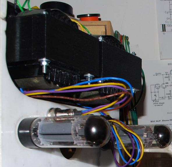
![]()
and at the bottom ...
... III. the power supply:
-
The power supply consists of two 500 VA transformers with 230/2x115 Volt winds rectifing using the russian Thyratron, TG1-2,5/4 (Xenon) one way. After all it outputs 390- Veff at the end for the amps. The forth 115V secondary winding is used for basic tube heating. The heating of the thyratron demands its own 5 Volt and up to 14 Ampere of current and is supplied by the third transformator. Transformators and transducers are decoupled from the metal frame using felt.
The rectifier, the Thyratron TG1-2,5/4 produces a shining purple plasma of ionized gas.
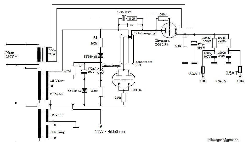
Because of the half-circle-rectification the filter capacitor is large. 1000µ/400V per channel. When powered up the thyratron is preheated about half a minute without the operation voltage. The"470µ/100V" capacitor C1 is loading slowly over the "260k" resistor until the glow lamp lights up and the voltage at the grid of the ECC82 is shifted from -20 Volt to nearly 0 Volt. The tube supplies now 10 mA switching current for the "antique" relay tube SR1 in the anode circuit with both systems. Now a swift discharge of the capacitor at a short power interruption is missing, - maybe over a relay... All circuits are basically preliminary! For example anti-interference measures and fuses are still missing.
On the right: relay tube SR1
![]()
IV. The tube heater:
1,5A DC-heater at 110V~ (The cathode ray tubes need hum-free heating voltage due to the circuit design here.)
All
EL34 are series-connected. So the allowed {Ufk} is not exceeded. ECC' and oscilloscopic
tubes are series-connected for the 1,5 Ampere and grounded
over the center pin.
With excess voltage in the parallel circuit (for example by partly removing the ECC tubes) the Zener diodes become conductive. The incandescent light bulb show the residual current. The contruction also serves as a distributor for all the heating cables.
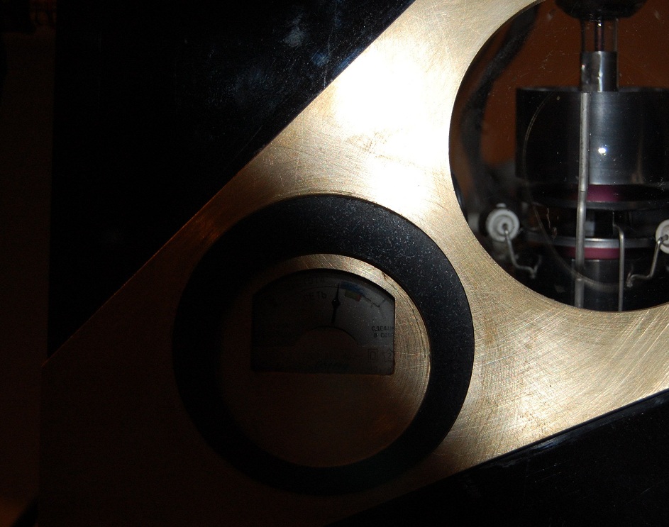
The voltmeter on the front shows the heating-voltage of the preamplifier tubes.
Assembly of the five thermistors (to the heating-circuit) on the back panel of the power supply. Despite some distance to the granite ...
...it is getting pretty warm here.
![]()
V. Preamp:
The pre amp with (high and low controller) is now completed. (ECC83, shelving filter) Circuit diagram and pictures comming up later. With the "crescent" the preamp is intended to be hooked-up, and also to cover up a scratch. (there i slipped off while counterboring)
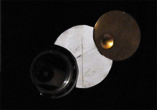
The controllers can be operated without troubles thanks to the ball bearings below.
![]()
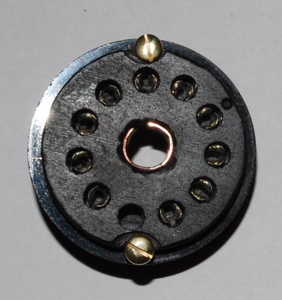
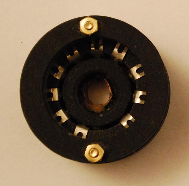
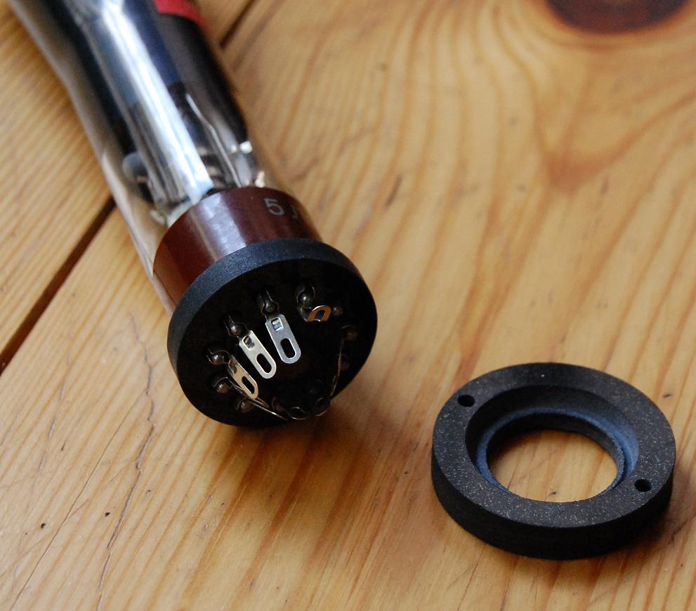
I couldn't find 11-polar tube holder for the 5LO38I cathode ray tubes ...
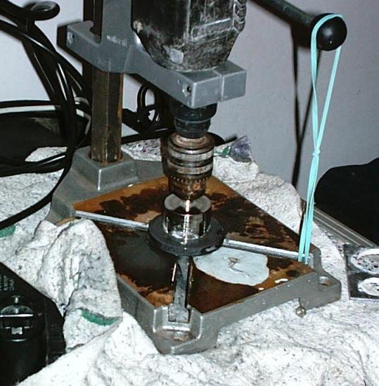
The sockets are assembled and cut out of the front panel-granite using drill bits of various size (diamond), some glas drills and a lot of water:
 |
 |
 |
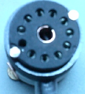 |
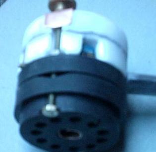 |
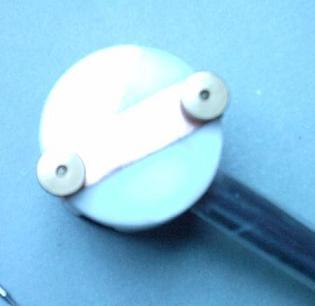
The granite sockets contain one further ring with lid made of offcut from the marble back panel.
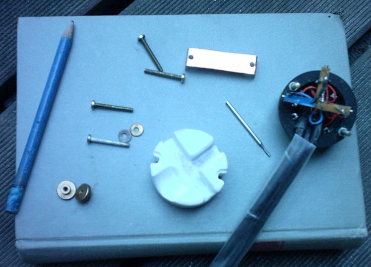
There the spindle trimmers for adjusting the brightness and sharpness are inserted. Thats compact and saves wires to the picture tube.
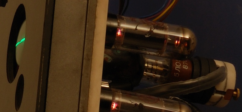
![]()
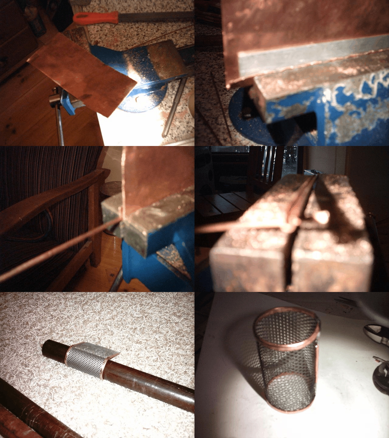
...briefly about the technical construction of the screen sheet:
![]()
The
heat development of the amp is actually emitted with good conscience only in
winter. The dissipation power of the tube heater >150VA
seams gigantic considering modern energy concepts. After a few hours the device
temperature levels out thru metal and stone at snugly 122°F. Between
the stone panels there is space for the air circulation from bottom up, along
the circuit. My worries about the output transformer influencing the
picture tube close by magnetically have been baseless. Sophisticated {MU} screening
could be omitted. I haven't weighed the whole box, but i estimate it to weigh
about 60 kilogram (132,277lb). The pictures shown have been taken over the building
periode with different cameras (own and borrowed), sometimes with and without
flash and are not modified in any way.
Meanwhile the circuit is operating a whole good while without problems. Including the relay tube 19 tubes and 0 transistors are integrated.
how tube amps operate (german)
![]()
![]()